
Which are the top five API 682 piping plans that dominate the oil and gas industry?
Keeping pumps running reliably in oil and gas operations depends on more than selecting the right mechanical seal. The way the mechanical seal is supported, lubricated and cooled has a direct impact on uptime, emissions control and maintenance. When a piping plan is well-matched to the application, it can extend seal life and improve overall asset reliability. When it is not, even a high-quality mechanical seal can struggle.
Why some piping plans dominate in practice
Although API 682 offers a wide range of seal support configurations, industry adoption is far from even. Certain plans are selected repeatedly because they strike a practical balance between reliability, cost and ease of operation. In many facilities, maintenance teams understand these plans well, reducing the risk of incorrect installation or operation.
The five plans discussed here are favoured because they typically:
- Address common process conditions found in oil and gas services
- Use simple, passive principles rather than complex auxiliary equipment
- Require minimal ongoing maintenance once commissioned
- Integrate easily with standard pump designs and layouts
Understanding why these plans work so well also clarifies when an alternative approach may be required.
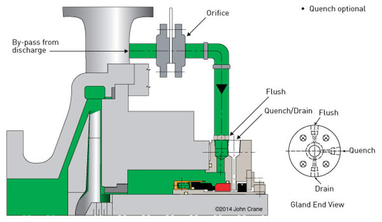
Plan 11
Plan 11 is the most used piping plan and is applied across a wide range of mechanical seal types.
How does Plan 11 work?
In a Plan 11 arrangement, a pipe connects the pump seal chamber to the pump discharge. As the pump operates, a higher pressure is generated at the discharge. This pressure differential causes process fluid to flow through the piping and into the seal chamber.
This continuous flow of liquid passes over the mechanical seal faces. The fluid lubricates the seal and removes heat generated by friction during operation.
An orifice is typically installed in the line to reduce the flow rate and protect the seal from exposure to full discharge pressure.
Why Plan 11 is so prolific
Plan 11 offers a straightforward and reliable method for supplying lubrication and cooling to a mechanical seal.
This arrangement is characterised by:
- Continuous flow of process fluid to the seal chamber
- No moving parts within the piping plan
- Minimal maintenance requirements
- No additional space required on the pump baseplate
Once implemented correctly, the system operates smoothly without requiring intervention.
Why other options may be required
Plan 11 relies on the pumped fluid being suitable for flushing. Other piping plans may be required when:
- The process fluid is too hot to act as an effective flush
- Abrasive particles are present that could damage the seal
- Air pockets are likely to form in the seal chamber, such as in vertical pump arrangements
- A dual seal arrangement is used, where lubrication and cooling are provided by a buffer or barrier fluid system
Plan 23
Plan 23 is commonly selected when direct cooling of the mechanical seal chamber is required.
How does Plan 23 work?
Plan 23 uses a closed-loop circulation system. Piping connects the seal chamber to a heat exchanger, forming a continuous circuit.
As the pump shaft rotates, a circulating device built into the mechanical seal induces flow within the loop. Process fluid moves from the seal chamber to the heat exchanger, where heat is removed. The cooled fluid then returns to the seal chamber.
The circulating fluid passes over the mechanical seal faces, providing lubrication and removing heat generated by friction.
Heat exchangers used in Plan 23 arrangements can be either air-cooled or water-cooled, depending on the specific application.
Why Plan 23 is so prolific
By arranging the flow in a closed loop, Plan 23 provides an efficient method of cooling the seal chamber.
Reasons for its widespread use include:
- The heat exchanger only removes heat imparted into the fluid at the seal
- Heat exchangers are typically smaller than those used in once-through cooling plans such as Plan 21
- Lower thermal load results in reduced maintenance requirements
- Flow is achieved using a shaft-driven circulating device, eliminating the need for an external circulation pump
Why other options may be required
Plan 23 is not necessary in all applications. Alternative plans may be selected when:
- The seal does not require direct cooling of the seal chamber
- Shaft rotation does not generate sufficient flow without an auxiliary pump
- A dual seal arrangement is used, with lubrication and cooling provided by a separate buffer or barrier fluid system
Plan 52
Plan 52 is the most used piping plan with dual unpressurised mechanical seals.
How does Plan 52 work?
In a Plan 52 arrangement, piping connects the space between the two seals to a vessel filled with a clean liquid. The piping forms a closed circuit between the seal and the vessel.
As the pump operates, a circulating device within the mechanical seal induces flow. The fluid circulates between the seal and the vessel, where it may be cooled using a cooling coil installed inside the vessel.
Any process fluid that leaks past the inboard seal is captured by the outboard seal and directed to a safe collection system. Vapours from the process leakage can be routed to a vent or flare system.
The vessel is typically fitted with pressure and level transmitters to provide continuous monitoring and to trigger alarms when critical values are reached.
Why Plan 52 is so prolific
Plan 52 provides effective containment for applications that use dual unpressurised seals.
Its widespread use is supported by:
- Containment of process fluid leaking across the inboard seal
- Suitability for lighter hydrocarbon services
- Low intervention requirements, with vessel level typically managed once per month
- Shaft-driven circulation without the need for an additional pump
Why other options may be required
Plan 52 may not be appropriate in all services. Other piping plans may be selected when:
- The process fluid is too hazardous for a solution with a low-pressure system
- Vent or flare infrastructure is not available to collect emissions
- Leaked process fluid condenses into a liquid, leading to contamination of the buffer fluid over time
Plan 53A
Plan 53A is a widely used option for dual pressurised mechanical seals.
How does Plan 53A work?
Plan 53A operates similarly to Plan 52, with a closed-loop circuit connecting the seal to a vessel filled with clean barrier fluid. Flow is induced by a circulating device driven by the pump shaft.
In addition, the vessel is pressurised using an external gas supply, typically nitrogen. A connection at the top of the vessel introduces pressurised gas, which exerts pressure on the barrier fluid.
The barrier fluid is maintained at a pressure higher than the seal chamber. This prevents process fluid from leaking across the inboard seal. Both seals are lubricated by the clean barrier fluid, while a small quantity of barrier fluid is injected into the pump process stream.
The vessel is equipped with pressure and level transmitters, enabling continuous monitoring and alarm settings.
Why Plan 53A is so prolific
Plan 53A is widely used because it provides full containment of process fluid while allowing the mechanical seal to operate on a clean barrier fluid.
Key characteristics include:
- Elimination of process fluid leakage across the inboard seal
- Lubrication of both seals using clean barrier fluid
- Low routine intervention, with level management typically required once per month
- Shaft-driven circulation without the need for an auxiliary pump
Why other options may be required
Plan 53A is subject to certain limitations. Alternative plans may be required when:
- Pressurised gas infrastructure is not available at the pump
- Process pressures exceed recommended limits; Plan 53A is limited to applications up to 10 barg (145 psig), as nitrogen can dissolve into the barrier fluid at higher pressures.
Plan 53B
Plan 53B is the most commonly selected piping plan for dual-pressurised seals, particularly in applications involving higher pressures.
How does Plan 53B work?
In a Plan 53B arrangement, piping connects the space between the two mechanical seals to a heat exchanger, forming a closed circuit filled with clean barrier fluid.
As the pump operates, a circulating device within the mechanical seal induces flow. The barrier fluid circulates from the seal to the heat exchanger and back again.
Pressure is applied to the barrier fluid using a bladder accumulator. Pressurised gas is stored inside the bladder, which transfers pressure to the barrier fluid without direct contact between the gas and liquid. This allows it to overcome the limitations of a plan 53A and operate up to much higher pressures.
The barrier fluid is maintained at a pressure higher than the seal chamber, preventing process fluid leakage across the inboard seal. A small quantity of barrier fluid is injected into the process stream.
The system is equipped with a pressure transmitter, enabling continuous monitoring and alarm settings.
Why Plan 53B is so prolific
Plan 53B is widely used because it provides pressurised barrier fluid without relying on a continuous external gas supply.
Reasons for its frequent selection include:
- Full containment of process fluid
- Lubrication of seals using clean barrier fluid
- Monthly intervention to manage barrier fluid volume
- Unlike many other pressurised piping plans, there is no requirement for a continuous pressurised gas supply or pressurisation pump, making it ideal for remote locations where extending utilities is difficult or costly
Why other options may be required
Plan 53B may not be necessary in all applications. Other options may be preferred when:
- The features of Plan 53B are not required
- Lower-cost arrangements can meet application needs
- High barrier fluid consumption or wide ambient temperature ranges would require large bladder accumulators
Applying API 682 piping plans in practice
Selecting the appropriate piping plan is crucial in determining the effectiveness of a mechanical seal.
John Crane supports oil and gas operators across the range of API 682 piping plan requirements, with mechanical seals, seal support systems and application expertise aligned to industry standards. Details on these plans, along with the full range of API 682 piping plan options, are available here.