
We take a unique approach to categorising mechanical seal piping plans in accordance with API 682. Our API seals are split into three zones, which are used to classify the types of piping plan affixed to each zone.
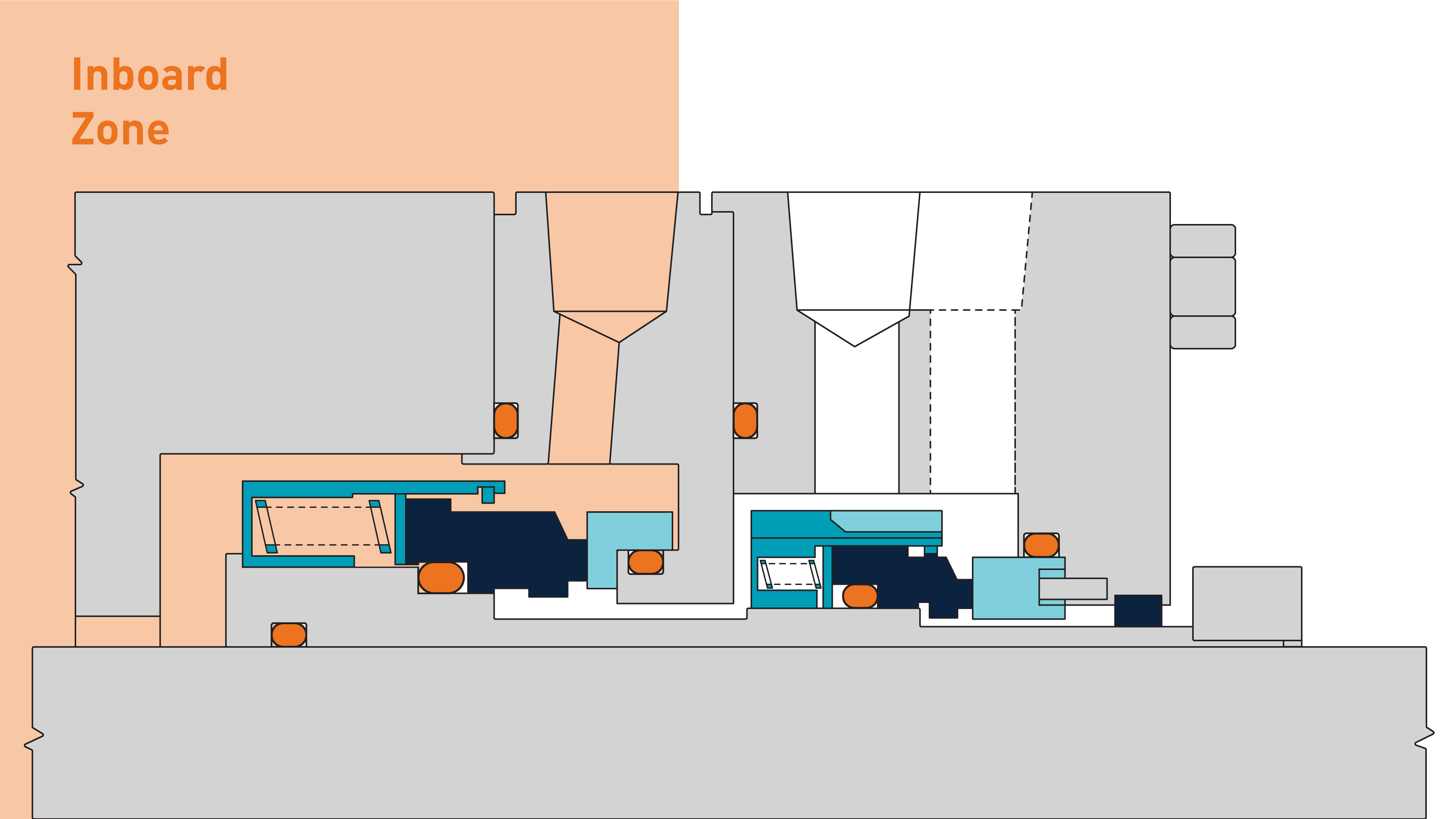
Inboard
These plans are attached to the pump’s seal chamber. They run on the process fluid, or a clean flush fluid in the case of Plan 32.
These plans are often referred to as 'Flush Plans' as many of them provide a flow of clean fluid over the inboard mechanical seal at a controlled temperature.
Their function is to cool and clean the mechanical seal.
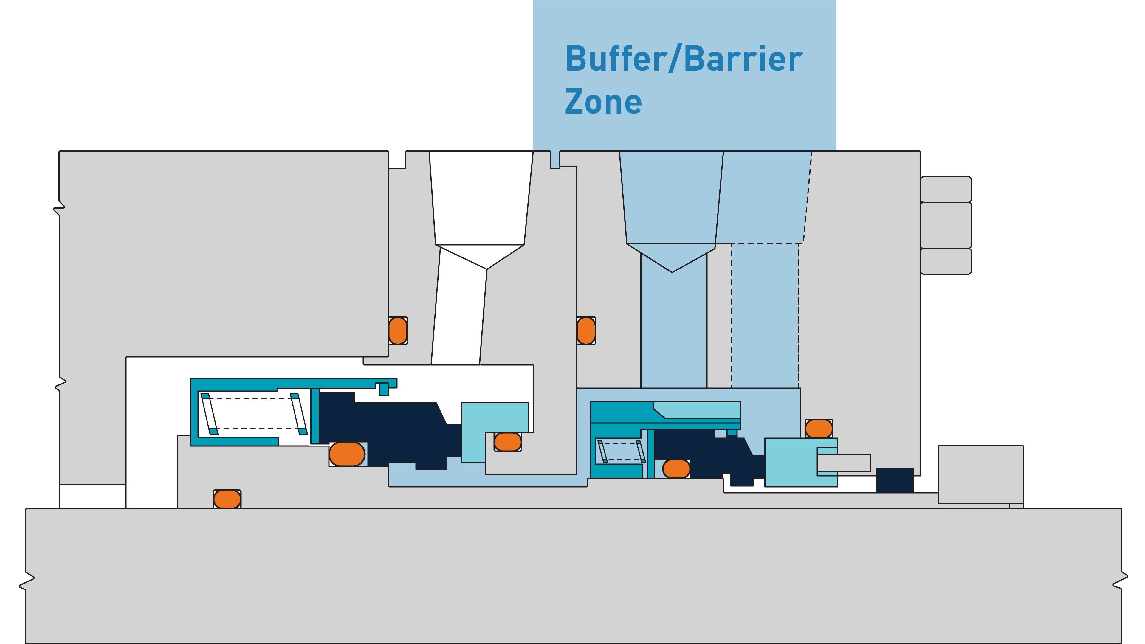
Buffer/Barrier
These piping plans are only on dual mechanical seals (Arrangement 2 or 3) and are connected to the space between the inboard and outboard seal.
These are the most complex piping plans involving multiple components and monitoring instruments.
The function is either to provide a clean fluid to lubricate the mechanical seals or to contain any process fluid that leaks past the inboard seal.
These piping plans are often required to control the pressure and temperature of the fluid at the mechanical seals and facilitate cooling flow.
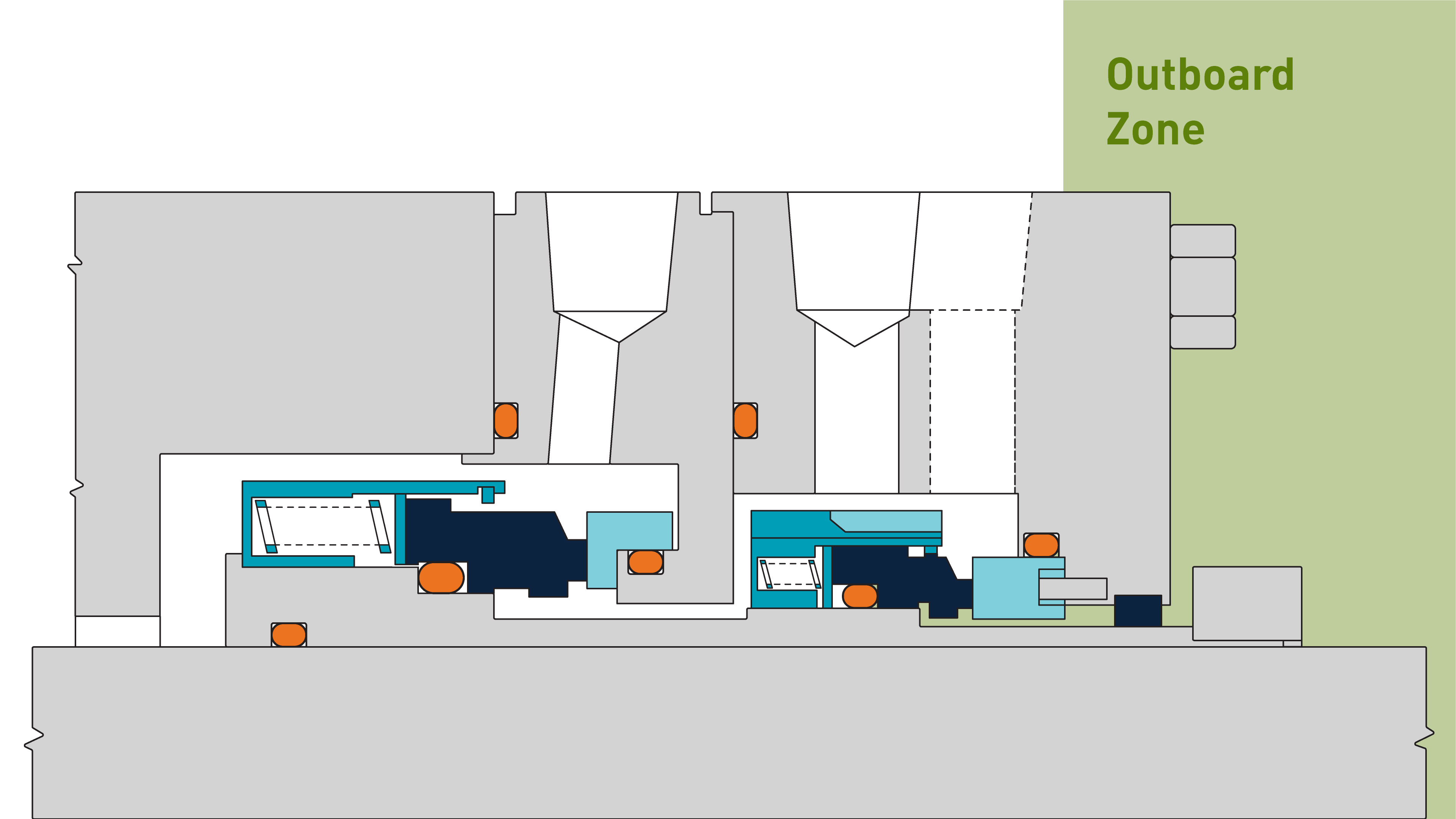
Outboard
These plans are attached to the mechanical seal on the atmospheric side. The plan could include a containment device, such as a bush or lip seal.
The area between the seal and the containment device is at atmospheric pressure and is often used to direct seal leakage to a safe location.
These plans are sometimes referred to as 'Quench Plans' as many of them provide a flow of clean fluid such as nitrogen, steam or water over the outboard mechanical seal. This cleans the seal or prevents icing, coking or the buildup of process leakage, which could cause damage and reduce seal life.
FAQs
What is the difference between buffer fluid and barrier fluid?
Buffer fluid (Arrangement 2):
- Lower pressure than process
- Leakage from the process flows into the buffer fluid
- Buffer fluid helps to collect and contain process leakage
- Used for monitoring and containment
Barrier fluid (Arrangement 3):
- Higher pressure than process
- Prevents process fluid from escaping
- Seals are lubricated by a barrier fluid, rather than the process fluid
- Used for the most hazardous or toxic services
What are API 682 seal piping plans?
Seal piping plans define how fluid is circulated, cooled, filtered or pressurised to keep seals operating reliably.
There are 32 piping plans defined by API 682 4th edition. The most common plans include:
- Plan 11 – Seal flush from discharge
- Plan 21/23 – Seal chamber cooling
- Plan 32 – External flush
- Plan 52 – Buffer vessel system
- Plan 53A / 53B / 53C / 54 – Pressurised barrier systems
- Plan 74 – Seal gas control panel
Plans are defined in Annex G of the standard, which has been expanded significantly in later editions.
What’s the difference between Plan 53A, 53B and 53C?
Plan 53A
- Barrier fluid reservoir pressurised by an inert gas source (typically nitrogen), with direct gas/liquid interface
- Simple and lower cost
- Risk of gas entrainment into barrier fluid at higher pressures (greater than 10 barg /145 psig)
Plan 53B
- Bladder accumulator isolates pressurising gas from the barrier liquid
- Able to achieve higher pressures
- Very widely used
Plan 53C
- Piston accumulator applies pressure to barrier liquid
- Automatically tracks pressure in the pump
- Used for applications with variable seal chamber pressures
What is API Plan 54 and when should it be used?
Plan 54 uses an externally pressurised barrier system, often with an external pump or supply. They are often engineered to suit the application and can range from small, simple systems to very large, complex ones.
Typical use cases:
- High heat loads
- Multiple seals sharing a system
- High-pressure applications
It offers greater flexibility but can be more complex to design.
Why does API 682 require a 28-day reservoir volume?
Reservoir systems must be regularly topped up with barrier fluid in order to continue functioning. API 682 considers the maintenance load of operating support systems. To reduce the workload on maintenance teams, API 682 specifies that buffer and barrier reservoirs must be sized to contain enough fluid for at least 28 days of operation without refilling.
This requirement heavily influences support system sizing but keeps the frequency or operator interventions to a manageable frequency.
How do I choose the right API 682 seal plan?
Typical decision factors:
- Process hazard level
- Environmental regulations
- Pressure
- Temperature
- Vapour pressure
- Maintenance capability
Simplified selection logic:
- Non-hazardous fluid → Arrangement 1 seal and simple plan, such as Plan 11 or Plan 23
- Moderate risk → Arrangement 2 seal and buffer plan, such as Plan 52
- High risk or emissions-critical → Arrangement 3 seal and barrier plan, such as Plan 53 or Plan 54
Selector for piping plans
Use the filters below to quickly find the right API piping plan—just select a plan type, your API seal type or both to narrow down your options.