The environment of a mechanical seal must be controlled for maximum seal life. API piping plans describe the various types of equipment which can be fitted to a mechanical seal, or even incorporated within the seal, to provide the optimum environment for the mechanical seal. To facilitate the combination of seal and system, John Crane categorises the areas within the seal into three zones:
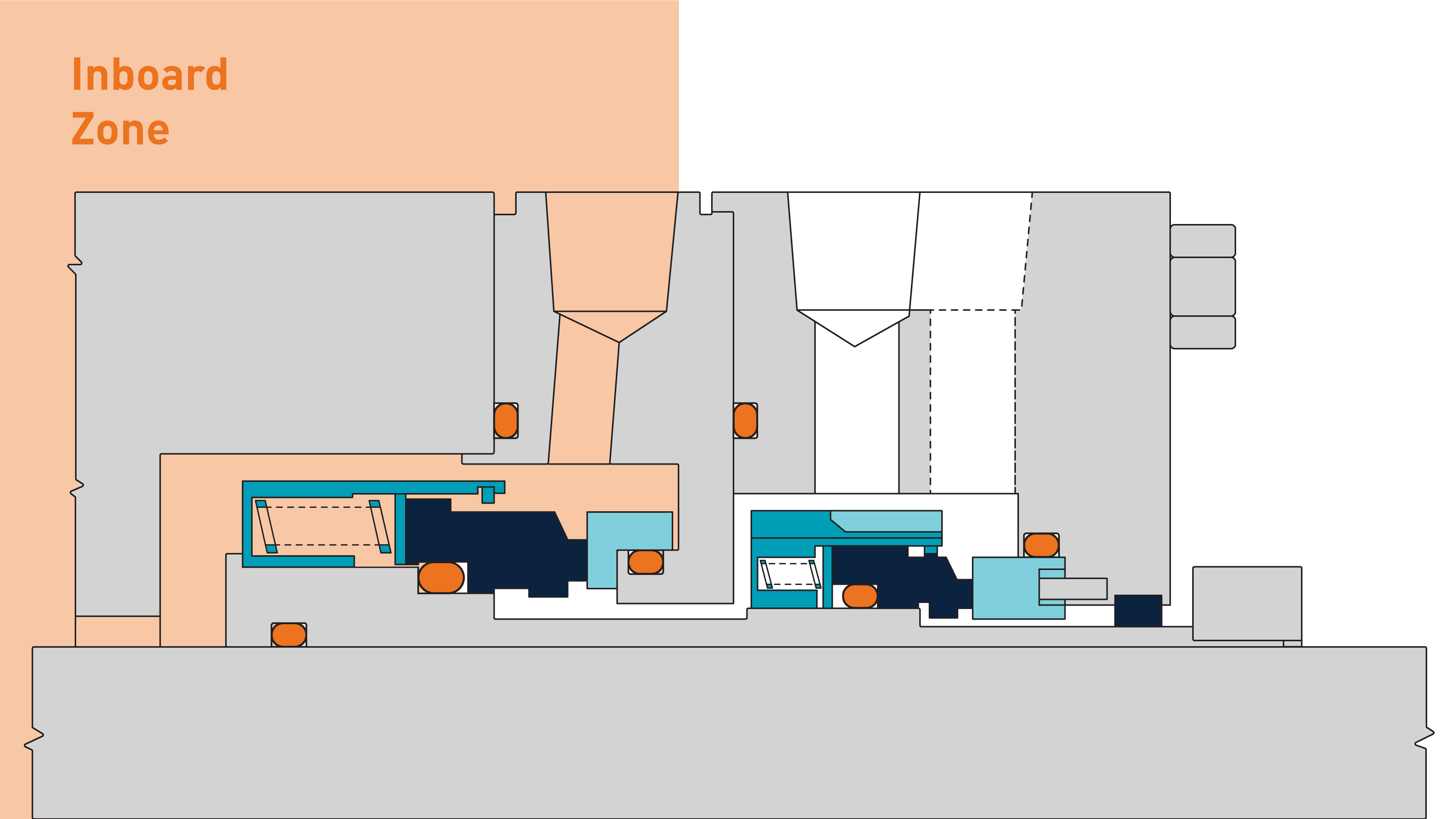
Inboard
This zone refers to the volume between the pump’s seal chamber and the inboard mechanical seal. It is filled with the process fluid, or a clean flush fluid in the case of Plan 32.
Piping plans fitted to the inboard zone are often called 'Flush Plans' as many of them provide a flow of clean fluid over the inboard mechanical seal at a controlled temperature.
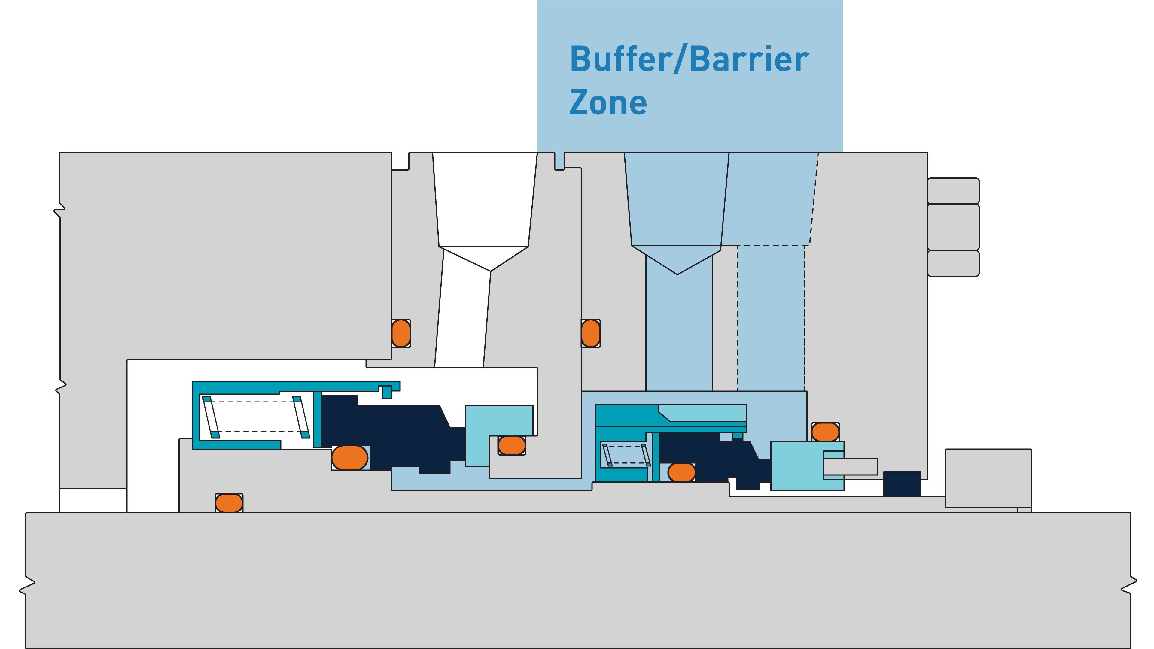
Buffer/Barrier
This zone is only present on dual mechanical seals (Arrangement 2 or 3) and refers to the space between the inboard and outboard seal.
This zone is filled with a clean buffer or barrier fluid and any process fluid that has passed across the inboard mechanical seal.
Piping plans fitted to this zone are the most complex, involving multiple components and monitoring instruments.
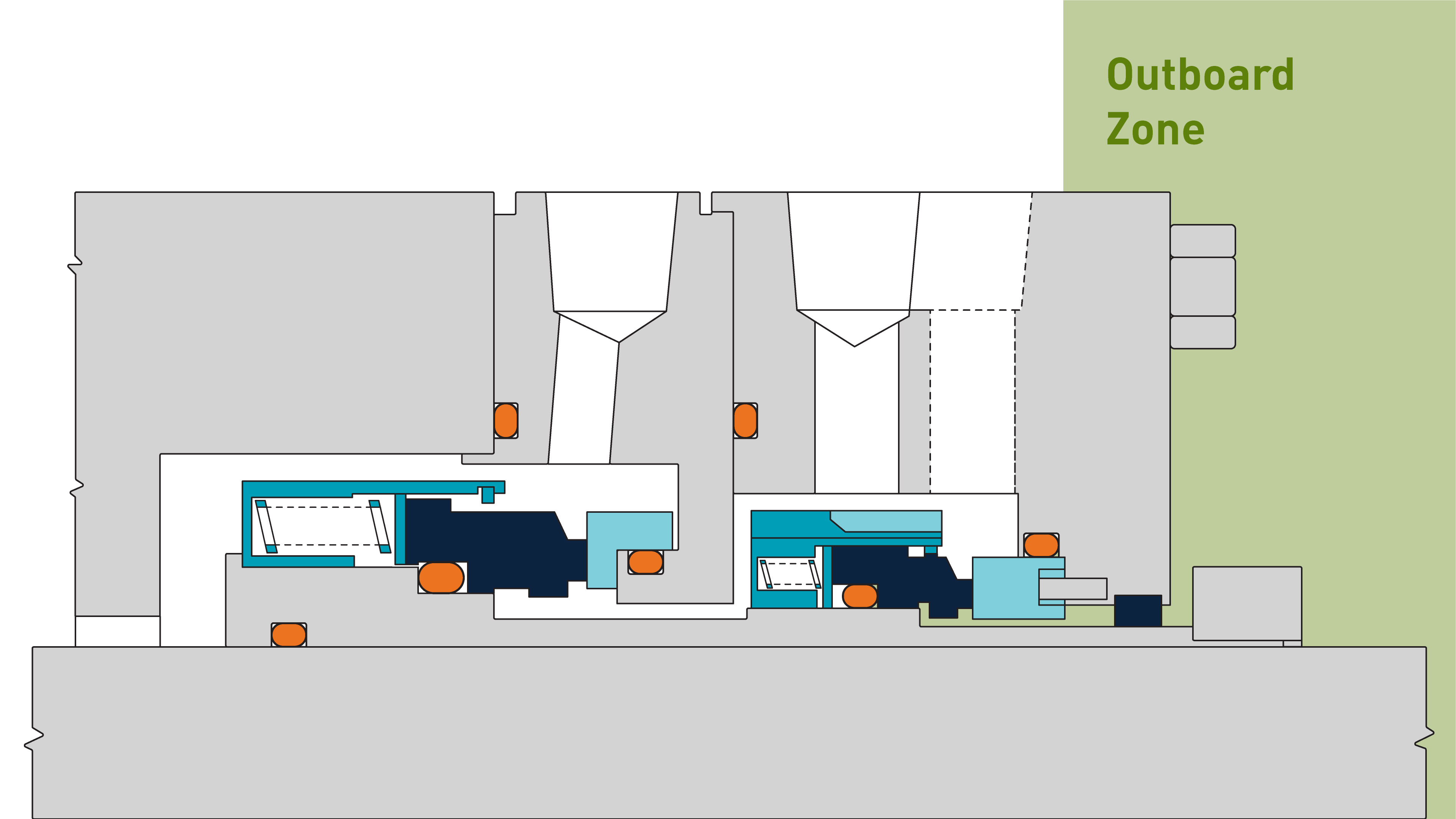
Outboard
This zone refers to the volume on the atmospheric side of the mechanical seal. The seal could include some kind of containment device, such as a bush or lip seal, which would be part of the outboard zone.
The area between the seal and the containment device is at atmospheric pressure and contains any fluid which has passed through the outboard mechanical seal, plus either atmosphere, or a quench fluid, typically nitrogen, steam or water.
Piping plans fitted to this zone are either dedicated to collecting or redirecting the fluid passing from the outboard seal, or functioning to clean the seal, or preventing icing, coking or the buildup of process leakage, which could cause damage and reduce seal life.
FAQs
What are the three seal arrangements in API 682?
- Arrangement 1 → simplest, lowest cost, highest potential for emissions to atmosphere.
- Arrangement 2 → improves containment but allows some process leakage into buffer fluid and a small amount of emissions to atmosphere. Used for some hazardous processes.
- Arrangement 3 → maximum safety; leakage goes inward toward the process. Zero-emissions to atmosphere under normal operating conditions. Used for the most hazardous processes and fluids which could damage the mechanical seal.
What causes API 682 mechanical seal failures?
Most common causes:
- Poor alignment
- Dry-running at startup
- Improper installation
- Excess heat via insufficient seal flush flow or heat soak effects leading to elevated seal face temperatures
- Pump operated outside of best efficiency point for long periods
- Contaminated fluids or abrasives
Practical field discussions frequently highlight installation and alignment issues as root causes.
What materials are used in API 682 seals?
Typical materials include:
- Silicon carbide
- Tungsten carbide
- Carbon graphite
- Hastelloy
- Stainless steels
Material selection depends heavily on:
- Corrosion resistance
- Temperature
- Lubricity
- Chemical compatibility
How long should an API 682 mechanical seal last?
Typical expectations:
- Average sites: 2-3 years
- Best-practice operations: 5-10+ years (API 682 performance expectations are 25,000 hours (3+ years) of continuous operation
Reliability depends more on application and installation than seal design alone.
Selector for seals
Looking for an API seal to go with an API piping plan? Find the right seal by selecting a plan type, a specific plan or both—the results will show the seals that match your selection.


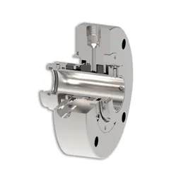


Type 2874HTC
Non-contacting, Metal Bellows, Outward Pumping Dual Pressurized Gas Lubricated Seal

Reliably sealing high and low temperature process fluids up to 425°C (800°F), the Type 2874HTC incorporates unique HTC (high-temperature, corrosion-resistant) metal bellows technology with non-contacting…
Type 2800MB Welded Metal Bellows Seal
Welded Metal Bellows Gas-lubricated, Non-contacting, Dual Cartridge Seal with Elastomeric Secondary Seals

The Type 2800MB is a state-of-the-art welded metal bellows, gas-lubricated, non-contacting seal for achieving 0.0 fugitive emissions for Maximum...