How Does Upstream Pumping Technology Fit Into API 682?
February 22, 2023
15 Minute Read

Upstream Pumping (USP) is a seal face technology unique to John Crane which adds the spiral grooves, commonly seen in non-contacting gas seals, to the inboard seal of a dual mechanical seal running on a liquid barrier fluid. The grooves draw in the barrier fluid and pressurize it as it reaches the tips of the grooves. This pressurization has the combined effect of causing the seal faces to “lift-off” each other, running with zero contact, and it can cause a low-pressure barrier fluid to leak backward by being pushed into a high-pressure process stream.
More information on this novel technology, including a video showing the operation of the spiral grooves, can be found here. Using this technology unlocks several benefits to mechanical seals including extending mean time between repair (MTBR), a substantial reduction in seal water consumption and lower costs. To take advantage of the unique benefits the technology provides, requires successful communication of the solution.

inboard seal of a dual mechanical seal running on a liquid barrier fluid
Proper Communication
The definitions and piping plans in API 682 are often used to communicate the features or operation of a seal and assume that all seals follow the basic principle of leakage flowing from high pressure to low pressure. This creates the following difficulties in communicating the working principles of USP seals to potential users and makes it difficult to match USP seals to specifications using API 682 as the common language.
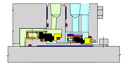
In this article, we will explain why it is most appropriate to treat a USP seal as if it were a dual pressurized seal (Arrangement Three Figure 1.) and be selected when this level of hazard protection or seal reliability is required, despite the unpressurized region between the inboard and outboard seal.
Figure 1: Arrangement Three seal

which is at a pressure higher than the seal chamber pressure
Buffer fluid or barrier fluid?
The clean fluid between the inboard and outboard seals of a dual mechanical seal can be named either buffer fluid or barrier fluid, depending on the function of the fluid and how it is used.
API 682 describes a barrier fluid as a pressurized fluid between the inboard and outboard seals. The reason that the name barrier fluid is used is because the fluid acts as a physical barrier between the process fluid and the atmosphere. A barrier fluid lubricates the inboard seal as well as the outboard seal.
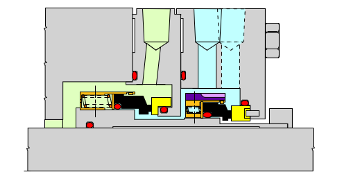
API 682 describes a buffer fluid as a fluid between the inboard and outboard seals, which is at a lower pressure than the seal chamber pressure. The reason that the name buffer fluid is used is because the fluid acts as a buffer between the process fluid and the atmosphere. The process fluid leaks into the buffer fluid, contaminating it. A small amount of the process fluid can then leak into the atmosphere through the outboard seal. A buffer fluid only lubricates the outboard seal, and the inboard seal is lubricated by the process fluid.
While the intermediate fluid in a USP seal is stored unpressurized, the fluid lubricates the inboard seal and all flow across the inboard seal is the intermediate fluid flowing into the process fluid. Therefore, all the behaviors and benefits of the intermediate fluid are the same as a barrier fluid.
In addition, while the intermediate fluid is stored in the system at low pressure, when the fluid is drawn between the inboard seal faces, it is pressurized by the spiral grooves. It then becomes a pressurized fluid and fits the description of a barrier fluid.
Therefore, while the intermediate fluid in a USP seal is stored at low pressure like a buffer fluid, it is more appropriate to describe it as a barrier fluid.
Seal arrangement
In API 682, the seal arrangement is a description of how the seal is constructed and helps to communicate its function.
API 682 describes an Arrangement Two (Figure 2) seal as a dual seal, with an unpressurized region between the inboard and outboard seal, or a dual unpressurized seal. The volume between the inboard and outboard seal is filled with either a gas or a clean buffer liquid.
Figure 2: Arrangement Two seal

which is at a pressure lower than the seal chamber pressure
API 682 describes an Arrangement Three seal as a dual seal, with a region between the inboard and outboard seal which is held at a higher pressure than the pump seal chamber pressure, or a dual unpressurized seal. The volume between the inboard and outboard seal is filled with either a gas or a clean barrier liquid.
By this simple description, it would seem to be most suitable to use the term Arrangement Two to describe a USP seal. However, this has the consequence that, when selecting a USP seal according to API 682, a USP seal would be treated as only having the safety and emissions capabilities of an Arrangement Two seal.
In terms of their function and the safety/emissions elimination, USP seals act like an Arrangement Three seal.
A suggestion would be to refer to USP seals as Arrangement Three, or that a special designation, is used to avoid confusion with traditional Arrangement Three seals. USP seals should be treated as being Arrangement Three for the purposes of their safety and emissions capabilities.
Seal configuration
API 682 uses configuration codes to add further detail to the description of the function and construction of a mechanical seal. The codes start with a number, signifying the seal arrangement (one, two or three) and then use combinations of letters to describe the functions of the seal(s).
The existing API 682 configuration codes recognize the code CW to refer to a contacting wet seal, and NC to refer to a non-contacting seal. API 682 assumes that an NC seal is a dry running seal where gas forms the fluid film lifting off the faces.
In addition, API 682 accepts the following configuration combinations for dual seals:
- 3CW for a dual pressurized seal where both inboard and outboard seal are contacting wet seals
- 3NC for a dual pressurized seal where both inboard and outboard seal are non-contacting gas seals
- 2CW-CW for a dual unpressurized seal where both inboard and outboard seal are contacting wet seals
- 2CW-SC for a dual unpressurized seal where inboard seal is a contacting wet seal and outboard seal is a contacting dry containment seal
- 2CW-SC(NC) for a dual unpressurized seal where inboard seal is a contacting wet seal and outboard seal is a non-contacting dry gas containment seal
A USP seal has a non-contacting wet seal at the inboard, and a contacting wet seal at the outboard. As discussed previously, a USP seal is best described as Arrangement Three. In addition, the onboard seal is both wet’ and non-contacting so a new code, NCW could be used to describe this seal. The full code for a USP seal would then be best described as:
3NCW-CW
Though arguably, 3NC-CW would also suffice.
Piping Plan
USP seals have different support system requirements than a traditional dual seal. While the initial assumption might be that an API Plan 52 would be the perfect solution, providing a reservoir of low-pressure liquid, there are several reasons why a Plan 52 may be inappropriate:
- Barrier fluid consumption in a USP seal is higher than a traditional wet seal would consume buffer fluid, therefore a traditional Plan 52 would require a large reservoir or frequent top-up activities
- Plan 52 has a vent connection to provide a safe route for leaked process vapors to a safe collection system such as a flare. There is no process leakage into a USP system, so this feature is unnecessary
Instead of an API Plan 52, there are some other common solutions for the construction of the support system, depending on the application.
Reservoir solution
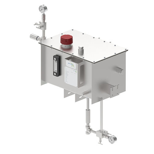
A common solution for a USP system is a reservoir of fluid positioned above the USP seal so that a volume of water is available for the seal, and a small head pressure is provided. In order to match the barrier fluid consumption, the reservoir is designed to be connected to a site water supply, and a float valve in the reservoir allows the level to be auto-topped up at the rate of barrier fluid consumption, without any operator intervention. These solutions are simple, robust and perfectly meet the needs of a USP seal.
The GS USP-R product, launched in 2022, is designed with this principle in mind. It has a modular design depending on the requirements for instrumentation, safety and seal water filtration.
This type of piping plan is sometimes referred to as a Plan 52M, signifying that it is a modification upon the principle of a Plan 52, providing a volume of low-pressure clean liquid.

Direct connect solution
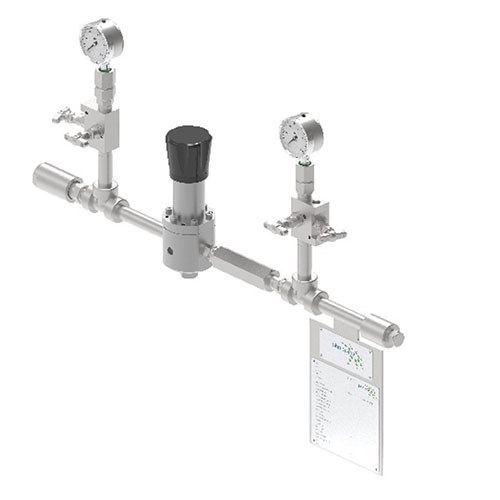
Another common solution is to connect the seal to a site water supply but without the intermediate reservoir. The water is treated, a pressure-reducing valve reduces the water pressure to the value required by the USP seal, and a non-return valve provides containment to prevent contamination of the water supply from the process fluid, should the inboard seal be damaged and process fluid enters the barrier circuit.
The barrier water can then either be routed to pass through the seal once, and then be directed to drain, or it can circulate several times throughout the seal. The direct connect solution also provides for the needs of a USP seal, in a smaller footprint than the reservoir solution, and the pressure control valve allows more control over the pressure at the seal. However, this comes at the cost of losing the stored volume of fluid in the reservoir, which can allow the USP seal to run for several hours if the water supply is interrupted.
The GS USP-D product, launched in 2022, is designed with this principle in mind. It has a modular design depending on the requirements for instrumentation, safety and seal water filtration.
This type of piping plan is sometimes referred to as a Plan 55M, signifying that it is a modification upon the principle of a Plan 55 using an external supply of unpressurized clean liquid.

A note on API Plan 99
Technically, the most appropriate piping plan designation for this piping plan is Plan 99, as this refers to an engineered solution that does not comply with the requirements of the pre-existing piping plans. However, simply using the term Plan 99 is an open description and does not tell us anything about how these plans operate, so 52M and 55M should be considered more useful terms to communicate the type of piping plan being supplied.
Conclusion
Following this article, a USP seal should be communicated and understood as:
- An Arrangement Three seal due to the safety/containment behaviors of the seal and that the inboard seal is lubricated by the clean intermediate fluid
- Using the configuration code 3NCW-CW as the inboard seal is wet and non-contacting, and the outboard seal is contacting wet
- Running on a barrier fluid as the fluid acts as a physical barrier preventing the process fluid from leaking into the atmosphere, and it becomes a pressurized barrier fluid when it is drawn into the spiral grooves
- Supported by a Plan 52M or Plan 55M Piping Plan as the commonly used support systems act as modifications on the classic API Plan 52 and API Plan 55 premises
More information on this novel technology, including a video showing the operation of the spiral grooves, can be found on the USP page of our website.
Partner with USP seal face technology experts
Are you ready to learn more about the benefits of using Upstream Pumping seal face technology? At John Crane, we have over 100 years of experience, so contact one of our experts today.